
KIMO: keeping things cool and on the go – Fan drives for building facility and industrial systems
Why power electronics for fan drives
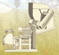
Fans and blowers are used for the widest range of applications when moving and blowing air. In addition to pure ventilation, important applications also include the cooling of equipment and systems and the climate control both of technical or biological systems as well as warehouses, residential and recreational areas.
Generally, fans and blowers operate for many hours of a year – even continually. This results in appropriately high operating costs with a relatively low capital investment costs. This means that the lifecycle costs comprise, to a large extent, the energy costs. Further, for most applications, three-phase induction motors are used for these types of drives. The speed of these drives can be adjusted in a highly efficient way – for example by using frequency inverters with the appropriate control characteristics.
Depending on the particular application, it is not sufficient to just connect the fan drive directly to the line supply through a breaker without using any closed-loop control. Technical requirements demand specific solutions which, today are increasingly being viewed from the energy cost perspective.
The starting characteristics of large fans, generally with high associated moments of inertia, require other solutions where it is important to control the starting operation without stressing the line supply as well as the mechanical system – electrically, thermally or as far as the force is concerned.
Other perspectives and recommended solutions are restricted to the large number of drives with three-phase induction motors.
Problems from the field – starting characteristics
Every drive must be initially accelerated from either standstill or a low speed. While for small fans this can be simply done using a breaker, for larger fans with higher power ratings, other solutions must be used:
- Mechanical jerk: Significant stressing of the couplings, slipping pulley belts, load on the fan mounting system
- Pressure surges: Filter overload, noise as a result of pressure surges in the ventilation duct
- Starting current: The line current is significantly increased (by a factor of between 5 and 8 of the rated current); power supply companies often specify maximum values, high motor temperature rise in the acceleration phase, high switch-on losses, extremely high inductive voltage drop as a result of the reactive current component
- Starting noise: Noisy drive belts, pressure surges, significantly increased motor noise, especially when changing poles
Previous starting solutions
Up until now, both mechanical starting as well as electrical starting equipment was used:
- Hydro-coupling start: Additional equipment using an additional oil-filled hydraulic coupling, in order to reliably handle even heavy-duty starting – the problem of high motor inrush currents on starting remains.
- Reactor starting: This is an extremely effective method but which only becomes effective above the center of the speed range above which the fan represents a significant load – the electrical problems when starting the motor remains.
- Star/delta changeover: Widely established, the power supply companies frequently specify this technique above a certain kW motor power, more control equipment is required in the form of contactor combinations, significantly reduced torque while the motor is accelerating
- Pole changeover: Requires pole-changing motors (2nd operating speed), good acceleration, high starting currents remain, voltage spikes when changing over, noise and an additional jerk when changing over
- Wound-rotor motors with resistor starting: Extremely good starting characteristics, not well established in the field due to the fact that special motors are required with sliprings and wound rotor
- Resistors in the stator circuit: This solution can practically only be used for low power levels, the starting jerk is reduced and the starting current is conditionally reduced (for 3-phase circuits)
- Voltage reduction using a transformer: By reducing the voltage, the motor starts with a lower magnetization. This is the reason that this principle functions the same as the star/delta changeover but only if the fan drive can accelerate with a significantly reduced torque
Electronic solution using soft-starting equipment
For those applications, where the load on the fan drive is significantly reduced at lower speeds, an induction motor can be very effectively and softly accelerated by reducing the voltage with soft starting equipment:
- Starting currents in the line supply are only slightly increased (approximately 200% rated current): Can also be used for weak networks
- Star/delta changeover is not required
- Jerk-free starting
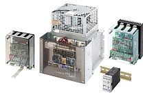
- Electronic starting equipment is compact
- High efficiency of the voltage adjustment
- Can be bypassed after run-up: No continuous losses. The small compact devices have an integrated bypass contactor.
- Continuous mode of operation
- Cost-effective series solution up to an operating voltage of 690 V even for extremely high fan powers of several 100 kW up to 1 MW
- Soft stopping possible: Soft, controlled down ramp
For those applications where the voltage can be reduced in operation (three-phase controller), permanent closed-loop control and speed reduction are possible
For specialists: Some physical basics of an induction motor
Most of the motors used worldwide are rugged induction motors which are available at a relatively favorable price. These types of motors have a characteristic relationship between their electrical and mechanical behavior even in spite of the different types of constructions, framesizes and various manufacturers. This is the reason that these types of motors can be easily used together with KIMO electronic devices without having to make extensive adjustments to the particular motor.
- An induction motor is also known as asynchronous motor. However, most motors run, in operation, at a constant speed which does not significantly deviate from the synchronous speed of the line supply: For example, 1435 RPM instead of a synchronous 1500 RPM
- When loaded, the speed only reduces slightly and when the load is removed, the motor speed increases again towards the synchronous speed
- Rugged drive: Most motors can be overloaded briefly, e.g. 200% – for many applications, this load is not even considered and the drive is simply used in this way
- High starting current: The starting current is generally between 500 and 800% of the rated current
- Versions with several changeable pole numbers for different speeds – widely established Dahlander circuit with a 2:1 pole ratio
The typical load characteristic of an induction motor is clearly defined in the starting characteristic: This characteristic indicates the possible torque as a function of the speed
When starting at speed zero, the motor has approximately 100 to 200% rated torque (and an inrush current of between 500 and 800% the rated current!). The motor only reaches the typical steep characteristic with a high maximum torque (stall torque) close to the rated speed: The motor only has its intrinsic high efficiency while it is operated in this steep part of the characteristic. The current drawn is then proportional to the load. Further, in this area, the speed is only slightly depending on the load.

The following well-known formula applies with a good approximation in the steep part of the characteristic:
Md ~ Ø x I
- Ø is the flux (magnetization) of the motor
- I is the current in the motor feeder cables
- Md is the torque at the shaft
Further, the following relationship applies:
Ø ~ U
This also clearly indicates how the motor behaves when the operating voltage is reduced:
Initially, with the load remaining the same, the current increases inversely proportionally to the voltage and the motor speed remains approximately the same as the operating voltage is proportional to the flux.
Due to the additional relationship
Mstall ~ Ø2
This also clearly indicates how the speed can be adjusted by reducing the voltage:
If the stall torque, which has now been reduced, is indirectly exceeded as a result of the decreasing flux, then the speed of the motor under load decreases. However, this control principle is only stable if the motor load torque decreases over-proportionally with decreasing speed, which is the case for a fan drive. This means that a stable operating point can again be obtained along the motor characteristic. However, this operating point with reduced operating voltage is associated with relatively high losses and with significantly increased currents when compared to frequency inverter operation. Further, the motor has a poor efficiency.
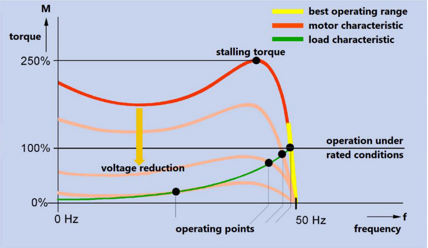
A load characteristic is now assumed, as example, which corresponds to a directly driven fan:
As the speed decreases, the required torque decreases according to a square law. In the reduced speed range, the fan is permanently operated in the starting range of the induction motor characteristic. At 50% rated voltage, only one quarter of the previous stall torque is available: The characteristic of the induction motor is correspondingly reduced and shifted downwards. The motor is continually operated in the starting range; unfortunately the current which is drawn does not decrease in proportional to the lower mechanical load.
Even more physics: An induction motor with frequency inverter
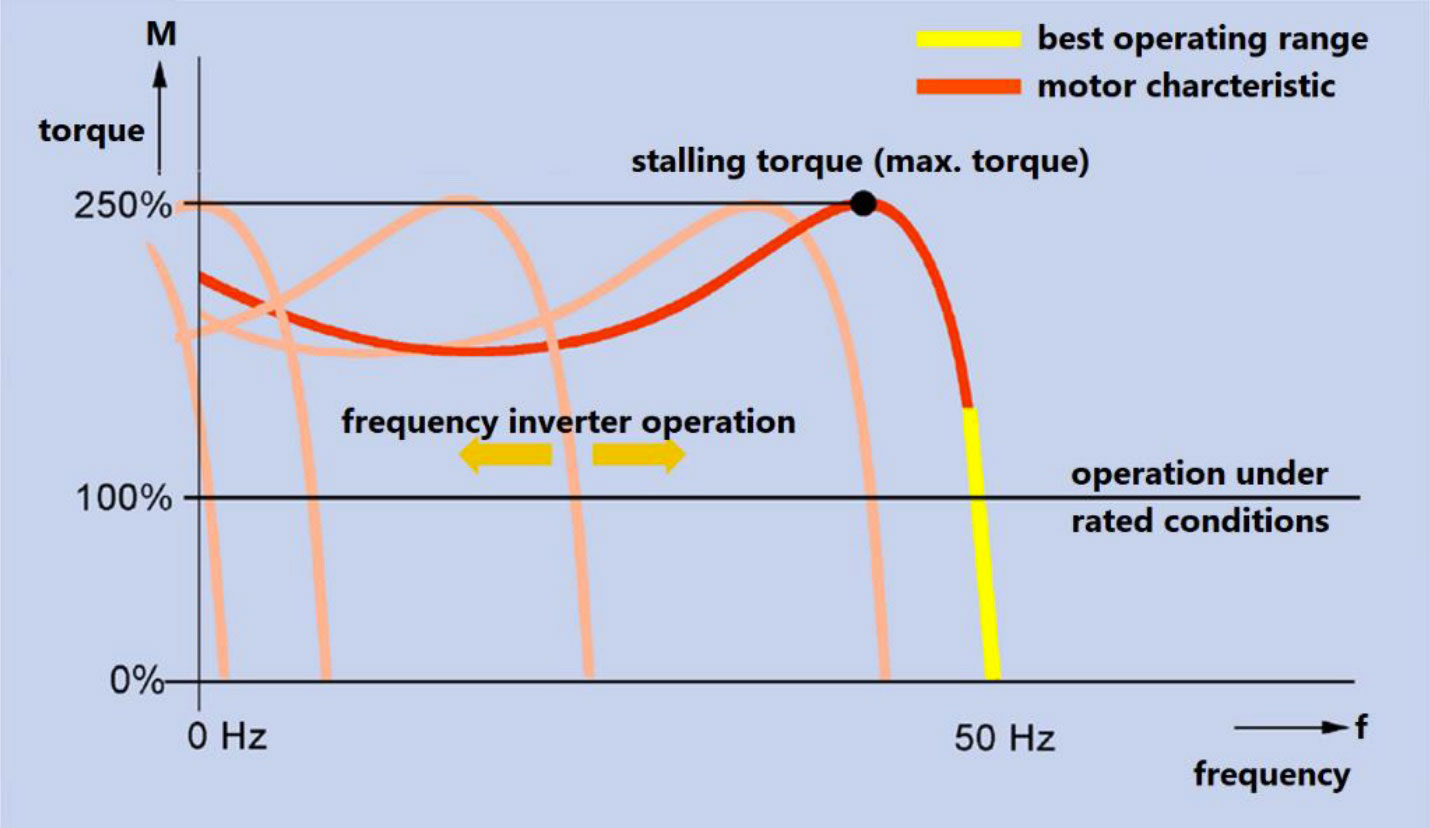
The optimum arrangement would be if an induction motor could be continually operated in its steep section of its characteristic. And it is precisely this which is possible if the motor is not connected to a rigid line supply with constant frequency where the only variable control parameter is its operating voltage, but the frequency can also be decreased (or, for higher speeds, also increased). A frequency inverter provides this type of supply. The frequency inverter changes both the operating voltage and also the operating frequency.
If an induction motor is operated so that with reduced operating voltage V, the operating frequency f is reduced to the same degree, then the flux Ø in the motor remains constant (constant main flux).
The following relationship applies:
Ø ~ U/ f
The motor then has a characteristic which corresponds to a continuous shifting of the steep range of the characteristic with a high associated efficiency. With the appropriate control, the motor no longer leaves this favorable operating range, and by shifting the sections of the characteristic, it is permanently operated in this range at each load speed. In order to further reduce avoidable losses as a result of the motor magnetization, for fan drives, the flux can be reduced with decreasing speed, because the torque which is demanded, also decreases: This means that the frequency inverter is no longer operated with a linear characteristic between the frequency and voltage (this results in a constant motor flux), but with a square-law characteristic, which is reduced to the same degree. This provides enough flux as is required for permanent operation.
Frequency inverter operation with reduced flux results in:
- Lower noise (reduces the magneto-restriction in the motor iron)
- Lower magnetizing losses
- Higher motor currents in relationship to the decrease (this is acceptable as long as an overcurrent condition does not occur)
- Low acceleration reserves for fast speed changes (for fans, this is essentially undesirable due to the faster pressure fluctuations)
Why are frequency inverters used for fan drives
For many applications, the fan delivery must be continually adjusted or adapted to a plant or system. The possibility of achieving the correct average fan delivery by switching-in and switching-out, is seldom a realistic possibility. Frequently, it is necessary to set or adjust the fan delivery. This is the reason that for some time now, conventional mechanical and electrical devices have been available which allow this adjustment to be made.
However, these techniques all have the disadvantage of significantly reducing the efficiency of the particular fan or blower. In some instances, the noise is increased to such an extent that this can only be implemented on a case-for-case basis or with additional noise reducing measures.
KIMO has many years of experience in the area of variable-speed drives so that together with you a changeover can be made to such drives, utilizing the cost-saving and user-friendly frequency inverter operation.
Previous closed-loop control techniques and their physical disadvantages
Today, in the field, there is still a high proportion of closed-loop throttle and vane controls and, to a lesser extent, speed adjustment using voltage reduction. Generally, transformers are used or electronically with three-phase controllers (the same as soft starting devices but with a permanent voltage reduction).
These methods will now be described in more detail. Fan and pump technicians are still being trained to apply and service them. In spite of their low efficiency they are still widely established.
Closed-loop throttle control
Closed-loop throttle control is based on the principle of changing the differential pressure of the impeller wheel in operation so that the fan delivery is reduced. Generally, this is achieved by reducing the cross-section in the air or gas duct, e.g. using adjusting flaps – the so-called throttle vanes. Unfortunately this has a high negative impact on the efficiency.
A continually increasing pressure drop is then obtained across the throttling element, which in turn reduces the volume flow of the gas or air because the fan or blower must work against an artificially generated counter-pressure. If the delivery pressure could be adjusted by reducing the speed, then the square-law relationship between the pressure difference and the volume flow would have a direct effect:
In order to reduce the volume flow by half, the speed would have to be reduced so that the pressure difference at the fan would be reduced to a fourth of the rated value. This is the case at 50% speed. Correspondingly, at 50% speed, only 25% of the torque is required; the drive power is then 12.5% of the rated value.
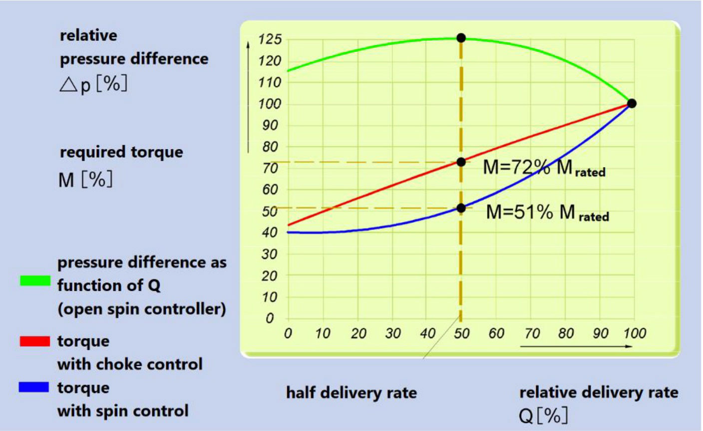
When closed-loop throttle control is used, the fan rotates at approximately a constant speed (the induction motor is operated, directly connected to the line supply and runs in almost synchronism to the line frequency with an extremely low slip). If the cross-section is reduced (throttled), initially, the pressure at the fan, in front of the throttling element, appropriately increases and the fan delivery is reduced. The pressure differential as a function of the fan delivery, is shown in the diagram. For a typical fan, for half of the volume flow, the pressure at the fan increases to 125% of its nominal value. The drive power required by the fan is only reduced to 72% of the rated value – even though the volume flow has been halved. If speed control were used, it would be physically possible to reduce this to 12.5%. This means that it is therefore 5.8x of the ideal case. However, the speed remains approximately constant so that the required torque which the motor must provide is also 72% of its nominal value.
Closed-loop vane control
For closed-loop throttle and vane control, the speed hardly changes when the delivery is changed (an induction motor rotates at an almost constant speed). This means that its drive torque is also proportional to the required drive power.
Using as an example a fan, where the delivery is to be reduced to half the nominal value, as a result of the vane control, there is still only a differential pressure of 75% of the nominal value. The required drive power is reduced to 51% and is therefore significantly more favorable than a pure closed-loop throttle control – but is still 4x value of the ideal case. Also in this case the speed remains approximately constant which means that the required torque decreases to 51% of the nominal value.
Energy saving by electrically controlling the speed
Using this control principle, the fan delivery is reduced by additionally causing eddies in the air duct. In this case, not all of the rotating fan surfaces are fully effective as a result of the eddies and, in some cases, flow reversal takes place. This technique also has a poor efficiency but is still better than pure closed-loop throttle control.
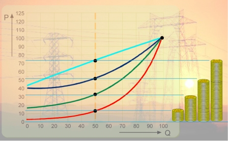
When the speed is changed, the drive torque decreases to the square of the speed. If a frequency inverter can be used to make this adjustment, then the drive power almost corresponds to the ideal characteristic P~Q³. When the speed is controlled by reducing the voltage, although the required drive torque also decreases according to a square law, the motor efficiency decreases drastically; the required power then has approximately the characteristic as shown below.
Closed-loop speed control using frequency inverters
When this technique is used, the motor is continually operated in its most favorable operating range with the steep speed/torque characteristic:
- Extremely high motor efficiency (in comparison to other control techniques), practically the same as when directly connected to a fixed line supply with rated speed
- High frequency inverter efficiency
- No high starting currents in the line supply
- When the speed is reduced, significantly lower line currents
- Can be controlled over the complete speed range
- The flux can be reduced for a typical fan load characteristic (reduced drive noise)
From the characteristic of generally used fans, it can be seen that as the speed decreases, the required drive torque generally decreases as a square law (with the exception of the frictional component caused by belts, bearings etc.). The air delivery is also reduced, but favorably to the same degree over the speed with an extremely high efficiency. Most ventilation tasks have a load characteristic that principally has the same square-law characteristic caused by flow losses in the filters, heat exchangers and air ducts. This means that speed reduction is the ideal control technique for these types of applications.
And it is precisely frequency inverters which are best suited to control the speed.
Genau das lässt sich mit einem Frequenzumrichter am besten bewerkstelligen.
Additional advantages of a frequency inverters
KIMO frequency inverters have an integrated control which can be used to simply realize other functions and closed-loop controls – even up to small automation tasks. Important cooling and ventilation functions can be simply implemented:
- Restart-on-the-fly circuit: The frequency inverter is powered-up with the fan still rotating (for example, the fan is slowly rotating due to the natural air flow)
- Closed-loop pressure control: The outlet pressure is kept constant and the pressure sensor which is used for the closed-loop control is directly connected to the frequency inverter and its auxiliary power supply is supplied from this.
- The noise of condensation fans used in refrigeration systems is reduced: In the nighttime, the noise of the heat exchangers of industrial and commercial refrigeration systems is frequently considered to be disturbing. The speed of these systems can be reduced, depending on the load and the particular time of day, using frequency inverters.
- Extremely heavy duty starting of fans and blowers: Using KIMO frequency inverters, fans with extremely high moments of inertia can be automatically accelerated, with the highest possible physical acceleration to the operating point along the current limit
- Phase synchronization: Using the KIMO phase control card, frequency inverters can be cost-effectively used to start large blowers, which, in rated operation, can be simply changed-over to the public utility without resulting in system transfer currents
