
State-of-the-art electronic devices for the wear-free braking of three-phase induction motors
Dr. John P. Gibson, Dr. Frank O. Hake
Electronic braking devices allow three-phase induction motors to be braked wearfree and offer a rugged alternative to mechanical brakes, especially for high moments of inertia- or high switching frequencies. Application examples from the field will describe state-of-the-art technology as well as new developments in this area.
1. Why electronic braking?
Three-phase induction motors are the most commonly used of all electric motors. Since frequency inverters have been available at a favorable price, three-phase motors are also being increasingly used for variable-speed applications instead of DC drives.Many machines and pieces of equipment have relatively high moments of inertia. When the machine or piece of equipment is powered-down, it continues to run for a correspondingly long time. Several examples from practice are listed in the table. In these examples, if the machine or piece of equipment is allowed to run-down in an uncontrolled fashion, this could represent potential danger for man or machine. For especially hazardous machinery, for instance, meat saws and woodworking machines, the appropriate regulatory bodies specify the maximum permissible braking times.The mechanical friction brake is the classic brake that is integrated in the motor in the form of a braking motor. For basic applications, and especially for applications with low braking energy, solutions such as these are extremely cost-effective and safe. However, as soon as the braking energy and the braking frequency exceed a certain limit, other solutions must be applied. The use of the existing drive motor as electrical brake has also widely established itself for such difficult applications. The possibilities of using the existing drive motor to brake are discussed in more detail in the following text.
2. Behavior of three-phase induction motors when braking with DC current
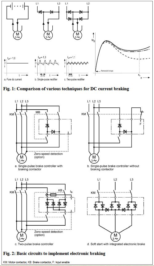
DThe behavior of a three-phase induction motor when braking with DC current is well documented e.g. [1],[2]. The three stator winding phases can be connected-up in many different configurations. When it comes to minimizing the amount of switching devices and wiring, then the circuit shown in Figs. 1a and 1b, with two phases connected in series, is almost exclusively used.The braking torque which can be achieved as a function of the speed results – in principle – in the usual speed/torque characteristic of an induction motor mirrored along the vertical straight lines through half the synchronous speed. The characteristic depends very heavily on the rotor design. At zero speed, theoretically, no braking torque is generated. In practice, there is a low braking torque due to remanence of the rotor core. For all of the braking circuits which inject a DC current into the rotor, the braking energy in the motor rotor is dissipated in the form of heat. If the braking effect of the load can be neglected, the energy loss when braking is theoretically the same as the energy loss when the motor starts. The motor should be appropriately dimensioned.
3. Electronic braking circuits with DC current injection
3.1 Conventional single-pulse rectifier circuits
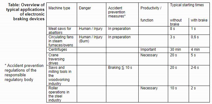
The simplest electronic braking circuit is the single-pulse rectifier circuit using a thyristor/diode combination together with an adjustable phase angle control (refer to Fig. 2a). A braking contactor is used to disconnect the braking circuit during normal motoring operation. When braking, a protection time of between 0.3…1.5 s is required depending on the motor size. A selectable timer stage limits the duration of the braking current to the predicted maximum braking time. Braking devices of this type are extremely compact – braking devices with extremely compact dimensions with the same width as a small contactor are available for motors up to 7.5 kW. These devices are simply snapped onto 35 mm DIN rails (refer to Fig. 6a).If the circuit illustrated in Fig. 2a (two phases connected in series) is used, this has the additional advantage that it is possible to fully electronically and automatically sense when the motor is at a standstill by monitoring the voltage in the third phase which does not have any connected device. As soon as the drive motor comes to a standstill, the braking current is electronically interrupted and, after the braking current has decayed, the braking contactor can be opened.Another development of the known single-pulse braking circuit is to use two thyristors instead of the thyristor/diode combination (refer to Fig. 2b). Operation without braking contactor is possible because the braking circuit is functionally disabled if the thyristors are not triggered. This version can be used to implement electronic braking for a minimum cost and also minimum space requirement in the control cabinet.The single-pulse braking circuits, described up until now, represent a very cost-effective solution, especially for lower power ratings. However, the current characteristic deviates significantly from pure DC current. This results in the following secondary effects:
- Noise is generated, caused by oscillating torques, especially at f = 50 Hz
- The RMS current value for the same braking effect is approximately 30% higher than for pure DC current. This means that the heat loss in the stator winding is approximately 70 % higher
- The braking torque at high speed is significantly lower than for pure DC current (refer to the torque characteristics in Fig. 1). The reason for this is the current harmonics generated by the phase angle control which generate undesirable motor torques, especially at high speeds.
3.2 Fully-controlled two-pulse braking circuits
These disadvantages can be essentially resolved by using a fully-controlled, two-pulse rectifier circuit (refer to Fig. 1c). For the same average braking current, the oscillating torques and the RMS value of the braking current are significantly lower for this circuit configuration. A braking device is essentially dimensioned according to the required braking current. Whereby, for the same braking current, the braking effect of a device with a two-pulse rectifier is approximately 10 % higher than a device with single-pulse rectification. A differentiation is made between:
- Applications, which require fast braking with the highest possible braking current. Generally, a braking current of approx. 2 x rated current is used as a basis when dimensioning the device whereby the braking time at this braking current is limited to 12 s.
- Applications, which require a long braking period (e.g. centrifuges) or even continuous braking (e.g. roller operations). In this case, the continuous braking current is specified as basis to dimension the device. At high powers, it makes sense to force-ventilate the braking device using a fan.
- Applications with multiple braking operations with miscellaneous drives.
A further development is to use current limiting which simplifies commissioning. The firing angle of the phase control is set at the device – i.e. the braking voltage is set. The actual braking current is obtained corresponding to the resistance in the braking circuit. However, this resistance depends very heavily on the size and dimensioning of the motor as well as also on the cabling. There is significant danger that an excessively high braking current could damage the braking device. Most customers do not have suitable measuring instruments to measure the braking current (DC current measurement).The maximum braking current of the device is automatically limited and commissioning significantly simplified using an integrated current limiting function. Further, a small braking device for braking larger motors with reduced braking torque can be used without any associated risk.
3.3 Combination of DC current brake with electronic soft starter
Devices which are used to softly and electronically start three-phase motors have advantages regarding the starting characteristic which can be selected and the reduced starting current. In recent years, several manufacturers have been offering devices which can start and brake three-phase motors. Most of these devices use an external braking contactor to initiate braking, whereby a brake switch-in delay of 0.3…1.5 s is provided depending on the motor size. After braking has been selected, these devices remain in the braking mode until the motor has reached a standstill. The braking contactor can only be safely opened after the current has decayed.A fully electronic technique (i.e. without braking contactor) is explained in the following text. This is used to implement electronic starting and braking. The basic structure of the associated circuit is shown in Fig. 2d. The three double arrangements of thyristor diodes represent the basic circuit of an electronic soft starting device. A part of this circuit, together with the two free-wheeling thyristors, located between the motor phases, forms a single-pulse direction-dependent braking circuit.
Using a control, synchronized with the line supply, it is possible to toggle between motoring and braking as many times as required. Typical changeover times for a 75 kW motor are:
- Changing-over from motoring (three-phase) to braking (DC current): 30…100 ms depending on the speed
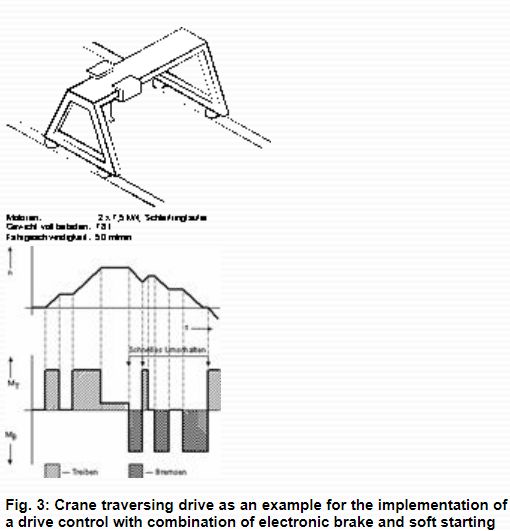
- Changing-over from braking (DC current) to motoring (three-phase), 20 ms including commutating over the braking current. This combination of motoring and braking is the basis of a rugged drive for two-quadrant operation. A typical application example includes traversing drives for gantry cranes (refer to Fig. 3). The following operating states can be set as a required and without any delay for the traversing drive depending on the position of the master switch:
- Motoring with a selectable drive torque.
- Continuing motion with the drive in a nocurrent condition, i.e. the crane gantry continues to move as a result of its kinetic energy.
- Electronic braking which can be set.
- Counter-movement with automatic standstill identification to initiate movement in the opposite direction.
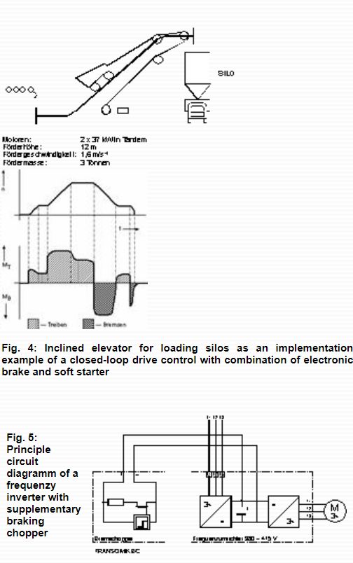
The circuit shown in Fig. 2d is admirably suited as basis of a drive with closed-loop speed control for starting, braking and positioning heavy machines and conveyor equipment independent of the load. The characteristic data of a system, equipped with this drive concept, is shown in Fig. 4. A typical device with combined braking and motoring functionality is illustrated in Fig. 6c.
4. Braking variable-speed drives fed from frequency inverters
Here we will only discuss braking when using AC frequency inverters with a DC link – so-called U inverters. When braking, energy is fedback into the DC link. This causes the DC link voltage to increase. Theoretically, it would be desirable to regenerate this energy into the line supply using a DC/AC converter. However, in practice, the equipment involved is far too expensive. The braking energy in the DC link must be dissipated using a braking chopper (Fig. 5). If a braking chopper is not used, or if the braking power of the braking chopper is not adequate, when the drive brakes, the voltage increases until the frequency inverter shutdown limit is reached. This results in operational faults. Relatively frequently, when engineering a drive, the braking chopper is incorrectly dimensioned. Typical examples include:
- High power fan drives which have a high moment of inertia.
- Hoisting drives, which must operate for a relatively long time when lowering a load.
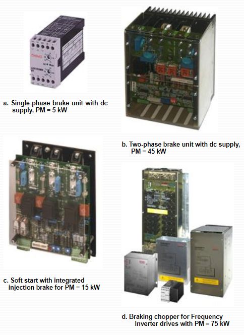
KIMO has developed a series of electronic braking choppers which can be especially used to subsequently increase the braking power of a frequency inverter. MOSFET and IGBT technology is used to switch the fixed braking resistor, which results in a simple and rugged design. Up until now, braking choppers have been implemented with a peak power of up to 1700 kW (refer to Fig. 6d).
5. Summary
Several wear-free electronic braking devices have been described for applications in the power range up to 200 kW. In so doing, the emphasis was placed on having a cost-effective design for rugged industrial use. The essential advantages of the braking devices described are
- for low power drives: Space saving in the cabinet using a new type of operation without braking contactor,
- for high power drives: Improved braking torque (especially at high speed) by using a fully controlled circuit,
- for drives with U frequency inverters: The braking torque is subsequently increased by using a supplementary braking chopper.
The regenerative feedback of the braking energy into the supply is an efficient and energy saving alternative. This can be solved by using an additional frequency inverter in so-called active-front-end solutions or with fully regenerative frequency inverters as implemented by KIMO with the TRANSOMIK U2 series. These frequency inverters with full power regeneration are compatible with the standard TRANSOMIK U1 range, which is available up to 15 kW.
Literature
[1] Sauer, H-G, König D, Goeke K-D: Bremsen von Drehstrommotoren mit Gleichstrom. antriebstechnik 31 (1992) Nr.6
[2] Schemanske, R: Electronic Motor Braking. IEEE Trans IA, Vol. IA-9, No. 5, Sept/Oct 1983
